How to Design a Spur Gear
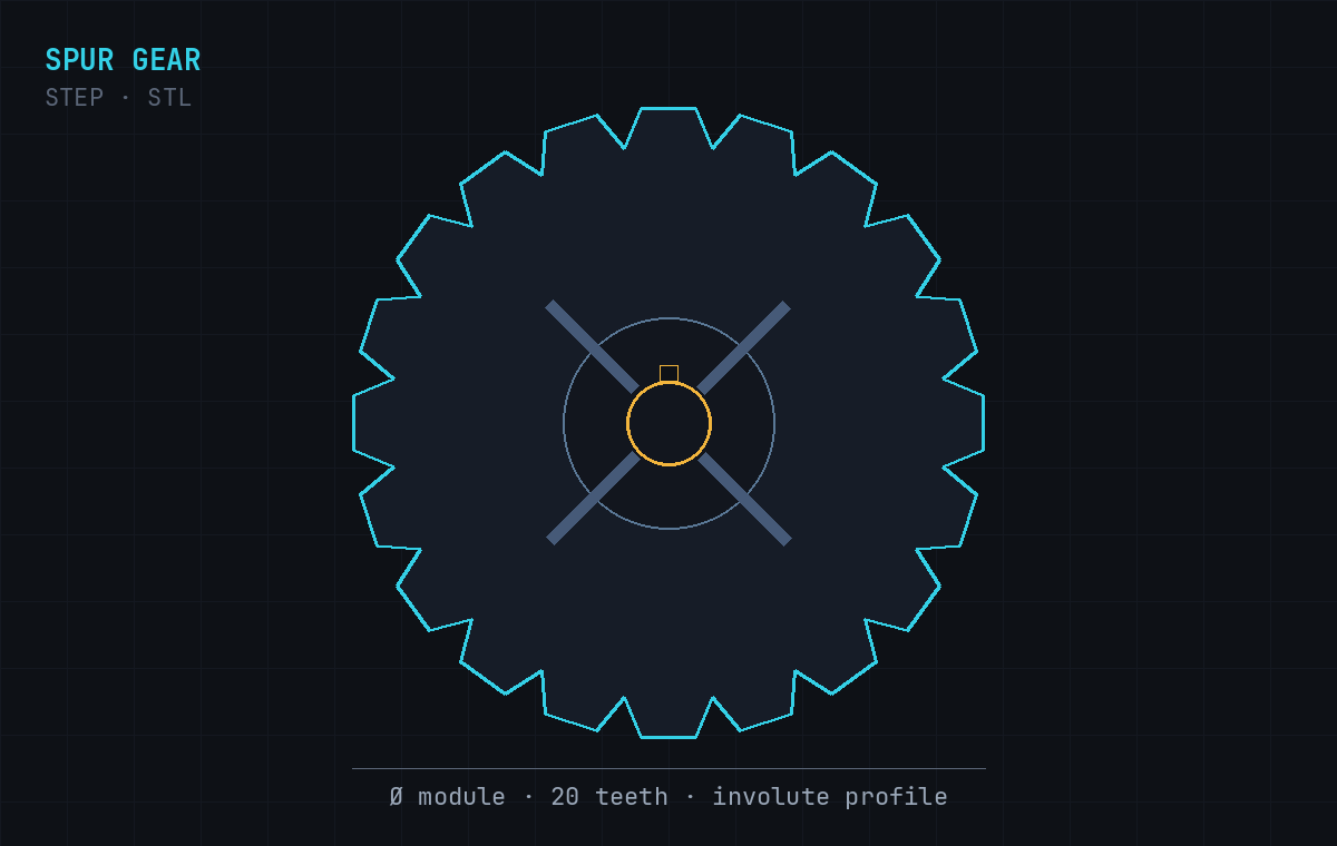
The spur gear is the most common gear there is — straight teeth cut parallel to the shaft, meshing with another spur gear on a parallel shaft to transmit rotation. It's the gear you picture when you hear the word. This guide covers the handful of parameters that fully define a spur gear, the formulas that tie them together, and how to turn a spec into a manufacturable CAD file.
What makes a gear a "spur" gear
On a spur gear the teeth run straight across the face, parallel to the axis of rotation. That simplicity is its strength: spur gears are easy to manufacture, efficient, and produce no axial thrust (unlike helical gears). The trade-off is noise — because each tooth engages its mate all at once along the full width, spur gears get loud at high speed. For most low-to-moderate speed drives, that's a fine trade.
The parameters that define a spur gear
1. Module (or diametral pitch)
Module (in mm) sets the size of each tooth. A larger module means bigger, stronger teeth. In inch-based systems the equivalent is diametral pitch (DP), which is teeth per inch of pitch diameter — note that a larger DP means smaller teeth, the opposite direction to module. Two gears can only mesh if they share the same module (or DP).
2. Number of teeth
Tooth count sets the gear ratio and, with the module, the overall size. It also controls the ratio between a pinion (the smaller gear) and its mate.
3. Pressure angle
Almost always 20° today (14.5° on older systems). It's the angle of the tooth flank and affects strength and smoothness. Keep it consistent across a mesh.
4. Bore, keyway and face width
The bore fits the shaft; a keyway or set-screw flat transmits torque; face width is how wide the teeth are (wider = more load capacity). These are the assembly details that turn a gear profile into a usable part.
The formulas that tie it together
Everything about a spur gear's size falls out of the module and tooth count:
- Pitch diameter = module × number of teeth (
d = m × z) - Outside (tip) diameter = module × (teeth + 2) (
m × (z + 2)) - Root diameter ≈ module × (teeth − 2.5)
- Center distance between two meshing gears = (d₁ + d₂) / 2
- Gear ratio = teeth on gear / teeth on pinion
Watch out for undercutting
Below roughly 17 teeth at a 20° pressure angle, a standard involute tooth starts to get undercut — the cutter removes material near the root, weakening the tooth. If you need a smaller pinion, you either accept the undercut, use profile shift (addendum modification), or raise the pressure angle. It's the most common trap when designing small pinions.
A quick design sequence
- Fix the gear ratio you need and choose tooth counts for pinion and gear.
- Pick a module from the load and space you have (bigger module = stronger teeth).
- Set the pressure angle (start at 20°) and check the pinion isn't below ~17 teeth.
- Confirm the center distance fits your housing.
- Size the bore, keyway and face width to the shaft and torque.
- Generate the solid, check the mesh, iterate.
Spur or helical?
If noise or high speed is a concern, consider a helical gear — the angled teeth engage gradually and run quieter, at the cost of some axial thrust. See how to design a helical gear for that path. For most straightforward drives, a spur gear is simpler and perfectly adequate.
From spec to CAD file
Once you know the module, tooth count, pressure angle, bore and face width, you don't need to draw involute curves by hand. Cadfai's AI Spur Gear Generator takes those as a plain-English prompt and returns a real parametric solid as STEP and STL — ready to drop into an assembly or send to be cut. If you're unsure which file to use downstream, see STEP vs STL.
Have your module and tooth count? Turn them into a STEP/STL solid in under a minute.
Let’s get started →